Technology description,
operating principle and main components of the system

The dual chamber floating Oscillating Water Column (OWC) Wave Energy Converter (WEC) device is the outcome of more than ten years of continued research and development to improve the hydrodynamic performance of WEC devices. The technology was invented (patented technology) by Rezanejad and Guedes Soares (2018) and was introduced for the first time in the 38th International Conference on Ocean, Offshore & Arctic Engineering (OMAE 2019) conference. The corresponding numerical and small scale experimental analysis data obtained by the R&D team were published later in 2020 and 2021 in the prestigious journals.
Fixed or floating Oscillating Water Columns (OWC) are devices with a semi-submerged chamber or an aperture open to the sea below, keeping a trapped air pocket above a water column. Waves force the column to act like a piston, moving up and down, forcing the air out of the chamber and back into it. This movement of air turns the air turbine at the top of the column, which is connected to an electrical generator that leads to electricity production.
The schematic plan of the new WEC device, the Double Chamber Floating Oscillating Water Column, is depicted in Figure 1. This new device is composed by a combination of two chambers that operate similarly to Floating Oscillating Water Column (FOWC) devices. In this technology, the fore chamber is faced directly to the incident waves. The mechanism of power absorption of this part is analogous to conventional OWC devices. Hence, it will be recalled hereafter as OWC part. The OWC part is supported by the underneath plate which is extended outside of the unit. The second chamber is employed in the rear part of the FOWC device which has indirect interactions with the propagating waves. The chamber has the duct shaped configuration similar to the Backward Bent Duct Buoy (BBDB) devices. Therefore, this part will be recalled hereafter as BBDB part of the device. Analogous to the conventional BBDB devices, this part is also interacting with waves downstream of the device. The wave energy is captured by the two chambers simultaneously and is converted to pneumatic power in the air pocket confined inside the chambers above the water free surface. One air turbine in each of the chambers (as the Power Take-Off unit) converts the pneumatic power to the mechanical and then to the electric power through an electric generator.
Each of the BBDB and OWC parts of this concept has their own dedicated turbine to capture the energy of the waves in a specific range of wave frequencies. The reason for considering two dedicated air turbines is that, each of the chambers has a specific resonance frequency that requires specific PTO damping to be imposed to harness the maximum power from the waves. The mutual interactions between the two chambers, the rigid body motions of the device specifically in pitch as well as the underneath plate in the OWC part of the system (Harbour plate shown in Figure 1) can significantly boost the tendency of the system to capture more energy (see the Innovation and Applications section for further details). Furthermore, application of dual chambers in this WEC technology imposes a natural phase shift in the two internal free surface elevations that assists the controllability of the system without the need to use complex and expensive “Re-active control” technology in the PTO system (see the Innovation and Applications section for further details).
Mooring system would be a single line that will be attached to the bottom of the WEC system near to the front end of the OWC part (as shown in Figure 1). The other end of the mooring attaches to a permanent anchor in the sea bed to keep the device in the desired position. The mooring system designed for this WEC device is relatively similar to the anchoring system in ships. Hence, similar to the ships, the connection of the mooring to the front end of the OWC part of the system causes the device to always remain in-line with the dominant wave direction in such a way that the BBDB part of the device locates on the downstream of waves. In other words, the WEC device can rotate around the anchor point according to the dominant wave direction. Hence, the OWC part of the device will always be located upstream of the waves accordingly. In this position, the device will have the best performance in terms of capturing energy of the waves because the specific mechanisms of energy harvesting by the OWC and BBDB parts of the device, require that they should be located on the upstream (OWC) and downstream (BBDB) of the waves, respectively, to be able to capture energy of waves efficiently in the desired frequencies.
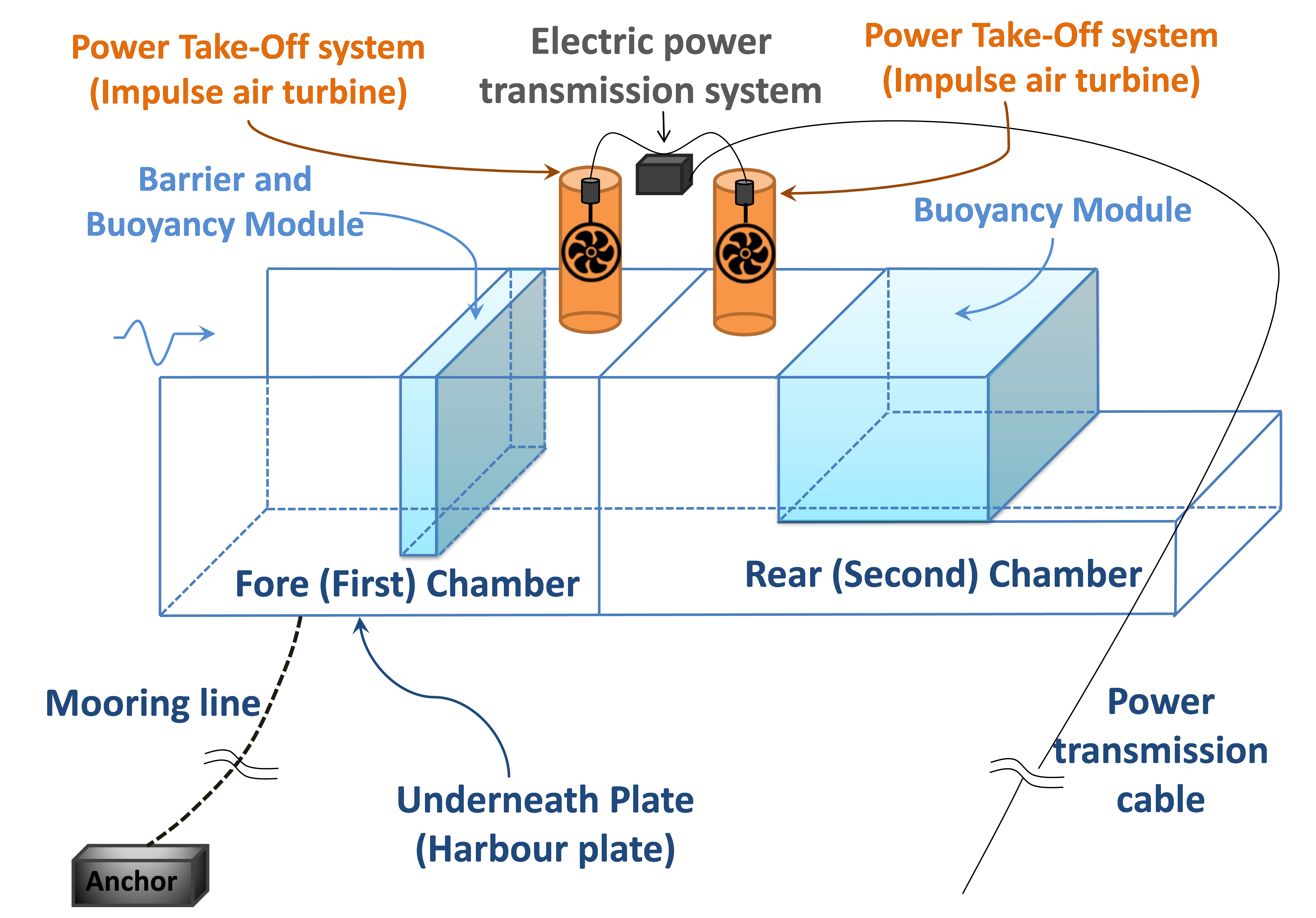
Figure 1: Schematic plan of the dual chamber floating OWC device
Maturity level of the WEC technology and its main sub-components:
Extensive analytical studies have been carried out for more than a decade to reach an efficient design of a floating OWC device capable of harvesting the energy of the waves efficiently, because poor efficiency is one of the main barriers to the commercial development of WEC devices as it leads to high energy production costs. Upon conclusion of the analytical and numerical investigations, comprehensive experimental studies using the 1/50 model were carried out to prove the conceptual design (the floating OWC model tested in the wave tank is shown in Figure 2). It is confirmed accordingly that (a) the devised WEC system has desirable hydrostatic and dynamic stability when interacting with waves (b) the mooring system acts properly to keep the device in desired position and (c) the floating dual chamber OWC device has reached the high efficiency that was expected from the previous numerical simulations) in the both regular and random wave conditions (see more details with corresponding references in Power Performance section).
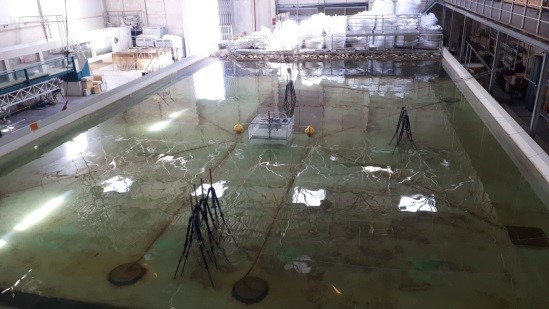
Figure 2: Schematic plan of the dual chamber floating OWC device
Installation strategy:
The structural design of the floating dual chamber OWC device is relatively close to the conventional barges. The system floats with its own natural stability (which is confirmed based on observations in the experimental test campaigns). In case that the device will be subjected to a force in the heave, roll or pitch directions (for instance when interacting with waves), the device will return to its equivalent position due to its natural hydrostatic restoring forces in those directions. Hence, the WEC device can be towed to the installation site by using only a tugboat (similar to the conventional barges). This process is easy, quick and robust compared to other complex marine transportation processes (i.e. compared to the case that the system should be transported on-board of other vessels). An Anchor Handling Tug Supply (AHTS) vessel is also needed to carry the anchor and chain of the WEC system to the installation site. The AHTS vessel will put the anchor in its desired position in the seabed and attach the chain to the WEC device by using its on-board cranes (for instance by using A frame crane installed typically on AHTS vessels).
Energy export strategy:
According to the specific geometrical design of the dual chamber floating OWC device, the produced energy can be exported or be stored on-board the device depending on the installation site, proximity to the other renewable energy systems and type of energy demand:
(1) The produced energy can be exported to the coastal zones using an underwater cable in case of deploying the WEC system in nearshore sites (which would be economically feasible). In the case of array application of the device and/or application in the proximity of other renewable energy producing systems (e.g. floating offshore wind parks, floating solar parks, tidal turbines) in an offshore area, the produced electric power can be transmitted to the shared electric power transmission station and exported to the shoreline by using a common underwater cable.
(2) The vacant space inside the two buoyancy modulus of the WEC device (Figure 1) can be engineered to store the produced energy by using hydrogen. In this case, the need for transmitting the energy using underwater cables would be eliminated, which can further reduce the energy production costs of the units installed in offshore zones. The produced energy in the form of hydrogen can also be used to support the energy demand of marine vehicles, which currently have an important role in increasing the environmental pollution.
(3) The energy produced by this WEC technology can also be used to desalinate the sea water and the fresh water can be stored inside the two floating modules of the system. In this specific application, the device can be implemented in nearshore areas of islands or less developed countries to support their fresh water demands.
Operation/maintenance strategy:
The operation of the system will be undertaken via the autonomous control system based on the real-time data recorded by various types of sensors. The rotational speed of the two turbines, air pressure inside the two chambers, generated power, rigid body motions and global position of the WEC device will be monitored automatically by implementing appropriate sensors. An alarm signal will be sent to the control station in the shoreline in case of detecting any abnormalities in the measured data. The measured data will simultaneously be implemented by the PTO control system on-board the device to maximize the efficiency of the system and change its operational condition to safe mode in harsh weather conditions. Moreover, the system should also have the capability to be controlled remotely from the control station in the shoreline in case that an urgent action is needed (e.g. shutting down the PTO system because of occurring failure or harsh environmental conditions).
As there are no moving parts operating inside the water in this WEC technology, the periodic inspection and maintenance of the PTO unit and other parts can be undertaken by using small supply vessels in the installation site. In case that a complex repair operation on the WEC device is needed to be undertaken in shipyards (for instance sandblasting to clean marine growth from the WEC body or undertaking overhaul process in the PTO unit or structure of the WEC), the WEC device can be easily towed to the desired location. In this case, the tip of the mooring line and underwater cable will be connected temporarily to a floating buoy to prevent their submergence.
References:
- Rezanejad, K. and Guedes Soares, C., 2018a. Dispositivo de conversão da energia das ondas (Wave Energy Converter Device), International (patent) application No.: WO2018PT00002 20180209 in: Treaty, P.C. (Ed.), F03B13/14 ed.
- Rezanejad, K. and Guedes Soares, C., 2019. Hydrodynamic investigation of a novel concept of OWC type wave energy converter device, Proc. 38th International Conference on Ocean, Offshore and Arctic Engineering. ASME Paper No: OMAE2019-96510.